| QUESITO 40 : In una analisi di Natural frequency compare il seguente WARNING[152]:Off-diagonal terms for torsional part of beam mass matrix are ignored. Use consistent mass to include these terms. Domando cosa significa. |
| RISPOSTA 40 : Questa informazione si trova sia nell'Online Help che nel Theoretical Manual. Aprendo l'Online Help nel capitolo "Solvers/Messages/Warning messages", si trova la sequente spiegazione: [152] Off-diagonal terms for torsional part of beam mass matrix are ignored. Use consistent mass to include these terms. When the lumped mass matrix is used for beam elements, the contribution to the mass matrix for torsional rotation may contain off-diagonal terms if the element?s axial direction is not aligned with one of the global coordinate axes. As off-diagonal terms cannot be considered in a lumped (diagonal) mass matrix, such off-diagonal terms are ignored and this warning is given. Praticamente quando si vede questo messaggio, è meglio usare l'opzione Consistent Mass. In generale, si può sempre usare l'opzione Consistent, essendo l'opzione più corretta matematicamente. Ma in pratica, l'opzione Lumped va benissimo ugualmente per la maggior parte dei modelli; per modelli molto grandi, Lumped è più veloce dell'opione Consistent, producendo resultati quasi identici. |
| QUESITO 39 : Sono in possesso del file IGES e STEP creati con INVENTOR di una struttura metallica reticolare. E possibile importare il file e trasformare tutti i componenti della struttura in questione in elementi beam ? E' necessario disporre del meshatore ? |
| RISPOSTA 39 : There is presently no automatic tool in Straus7 to convert a file like the one you have sent into an equivalent beam element model. CAD files like this are typically meshed into plate/shell elements, but for this particular structure, a beam mesh is more appropriate. Our advice would be to rebuild the geometry as lines in the CAD program and import it into Straus7 via DXF, then assign the section shapes. However, we do have under development a tool that attempts to do precisely what you have asked. This tool is not ready for release, but in the hope that it can help you, we have run the tool on your model and have extracted the beam elements you can see in the attached ST7 file. Obviously this is not yet in a state that can be analysed, and a lot of extra work is required to correct the cross-section geometries and connections, but it could save you some time. |
| QUESITI E RISPOSTE 38 : D1) In un'analisi nonlineare è necessario definire un diagramma momento-curvatura-azione assiale M-CHI-N, in modo che ad ogni iterazione si aggiorni per la sezione l'opportuna curva M-CHI per il valore corrente N, è possibile con la nuova release? R1) The moment-curvature option does not offer the possibility of coupling m-k diagrams with axial force. For this capability we recommend the nonlinear fibre stress option, described in the attached Webnote, which is much more powerful and flexible. D2) E' possibile definire legami costitutivi sigma-epsilon a trazione e compressione non simmetrici? E lo stesso per diagrammi M-CHI? R2) Yes. D3) E' possibile con la nuova release definire un elemento beam un legame Azione assiale-Spostamento con comportamento bilineare non simmetrico a trazione e compressione? R3) Yes. |
| QUESITO 37 : Devo fare una operazione con Straus7 che è segnata come nuova funzionalità della versione 2.4. L'operazione è la proiezione normale a superfici. In pratica ho alcuni plate uniti tra loro, ma orientati diversamente nello spazio (non stanno su unico piano), ed ho una beam che vorrei si potesse estrudere in un plate normale ai plate già esistenti. Non riesco a svolgere l'operazione. Il software non fa nulla. Ho provato a fare un caso elementare con un solo plate ed una sola beam ma il comando extrude to surface con flag su Source (plate) Normal non funziona. |
| RISPOSTA 37 : The option "Source (Plate) Normal" applies to the extrusion operation only when plates are the Source, not when plates are the Targets. If you are extruding a beam to a plate surface, the option is not applicable; in this case only the Conical and Parallel options are relevant. You can find more information about this in the Online Help. |
| QUESITO 36 : Mi servirebbe una spiegazione su un errore che mi da il solutore in Linear Static. In particolare mi compare questo messaggio: Global Stiffness Matrix Singular at Equation 98: Pivot = 0.000000E+00 (Node 107 RZ) *ERROR[ 4]:Global stiffness matrix is singular. *Solution terminated on 30/01/2014 at 16:00:41 *Solution time: 2 Seconds *SUMMARY OF MESSAGES *Number of Notes : 0 *Number of Warnings : 0 *Number of Errors : 1 Quindi ho un errore sulla matrice di rigidezza e quindi perdo la relazione tra forze statiche e spostamenti. Ho controllato il nodo 107 e non ho trovato errori evidenti (non so cosa significhi RZ e Pivot). |
| RISPOSTA 36 : The singularity occurs because there are some nodes that have no rotational stiffness. The model uses both Beam elements (which support six degrees of freedom per node) and Truss elements (which are only axial elements so they do not support bending, although they support torsion if required). At Node 99, which is on a truss at the other end of Node 107, you have only four Truss elements connected. Here there is no rotational restraint so the global matrix is singular. You need to ensure that all active degrees of freedom connect to elements that can provide stiffness. It seems that at least some of your Truss elements should really be Beam elements. |
| QUESITO 35 : Allego un file in cui ho svolto un'analisi non lineare del medesimo modello inserendo delle molle non lineari per simulare il terreno a tergo di una paratia. Inoltre viene simulata una fase di precompressione mediante cavi verticali. Anche in questo caso, la nuova versione risponde diversamente dalla versione 2.3. In pratica con la versione 2.3 il modello converge facilmente come sempre e senza problemi, anche perché non c'è niente di complesso, mentre nella nuova sembra non trovare delle soluzioni. Forse anche qui è un problema di taratura di alcuni parametri che è necessaria per la nuova versione. |
| RISPOSTA 35 : Unlike Straus7 R23x, in R24x support attributes such as Beam Support, Plate Support, etc, are now Freedom Case dependent. This means that in the load incrementation table (Solver/Load Increments) the freedom case containing these attributes needs to be selected. In the model you have sent us, no freedom case is selected, therefore the Beam Support attributes are excluded from the solution rendering the model unsupported. By activating the freedom case, the solution will proceed. This change in R24x makes the use of support attributes much more powerful and flexible than in previous releases, especially when construction sequence analyses are conducted. |
| QUESITO 34 : Vi contatto per avere un aiuto nella corretta modellazione di un problema di "contatto". ll modello in oggetto vuole simulare il rinforzo di un solaio esistente in cap con linserimento di una struttura metallica IPE140 disposta al di sopra. Il contatto tra le due avviene puntualmente con elementi in neoprene di altezza 5cm. Utilizzando elementi di contatto zero gap e risolutore non lineare volevo simulare la completa deformazione del neoprene e il successivo contatto tra lorditura in acciaio e quella in cap. I risultati non sono soddisfacenti in quanto superati i 5cm di deformazione del neoprene gli elementi non entrano in contatto. |
| RISPOSTA 34 : Please have a look at the axial force in the contact elements at the last increment and you can see that the contact elements are in fact active. Most of them become active at Increment 7. You can check this by showing contours of beam axial force on the contact elements (hide the other beam types by "View/Show by Type/Property"). Of course contact can only occur where there are contact elements, so if you need to consider the distributed contact between the current contact elements (i.e. along the whole length of the beams), then you will have to subdivide the beams and insert additional contact elements to prevent the sagging between contact elements. Finally, you need to keep in mind that the total displacement will exceed 5 cm because the structure as a whole will deflect, so it's not just the relative movement that you need to consider. The relative movement between points with contact elements will be limited to 5 cm, but the total will not be. |
| QUESITO 33 : 1) NEL FILE DI LAVORO E NEL SOLUTORE NTA POSSO LANCIARE SOLO UNA COMBINAZIONE DI ACCELEROGRAMMI. PER ESEGUIRE ALTRE ANALISI CON ACCELEROGRAMMI DIVERSI COME POSSO FARE ? - 2) LA COMBINAZIONE DI PIU' ACCELEROGRAMMI COME PUO' ESSERE GESTITA DA STRAUS7 ? |
| RISPOSTA 33 : The Linear and Nonlinear Transient solvers allow the input of up to three accelerograms for base acceleration problems, one accelerogram for each of the global Cartesian directions. If you need to consider multiple accelerograms, then multiple runs of the solver are required. If you need to superimpose the effects of multiple accelerograms, then you can produce effective combined accelerograms by combining them before applying then to the solver. The effect will be the same in terms of load because the accelerograms simply produce equivalent inertial force. |
| QUESITO 32 : Devo svolgere l'analisi dinamica di una struttura in muratura modellata con elementi Brick. Il legame costitutivo scelto per la porta è elastico lineare (scelto volontariamente per non rendere l'analisi troppo onerosa in termini di tempo). Al contempo vorrei inserire un adeguato DAMPING RATIO per tener conto dello smorzamento. La forzante applicata alla base è un accelerogramma. La risposta che ho ottenuto in termini di accelerazione risulta indipendente dal Damping Assegnato. CHIEDO dove sbaglio. |
| RISPOSTA 32 : The Damping Ratio parameter defined in the element property sets is not used in linear or nonlinear transient dynamic analysis. Its purpose is for the calculation of an effective modal damping ratio in Natural Frequency Analysis. This is described in the Online Help, but in brief, it allows you to define different ratios for different materials, then calculate the modal damping ratios based on the participation of each element to the total (modal) response. These calculated damping ratios can then be used in linear modal superposition analyses such as Spectral Response and Harmonic Response. For the inclusion of damping in a masonry structure, the most effective approach is to use Rayleigh Damping. This is selected on the solver dialog for the Linear and Nonlinear Transient solvers. This is also described in the Online Help. |
| QUESITO 31 : Dal programma vedo che è possibile attribuire degli ID (n° d'identificazione che si può attribuire ai vari elementi). Non sono finora riuscito però dal manuale a capirne l'utilità. Forse è un po' come i groups: una maniera per ragruppare degli elementi anche diversi come plates e beams ? |
| RISPOSTA 31 : There a number of uses to IDs. First of all they can be used just like groups, to define collections of entities. They can also be used as Selection Sets, since once an ID is assigned, you can select them using Select/by ID. Some users also use IDs for their post-processing and design checks. Because an ID never changes, whereas an element number can change when elements are added or deleted, the ID can uniquely identify a particular element, irrespective of numbering changes. API users can also use IDs to help with their development. |
| QUESITO 30 : Vorrei sapere se è possibile spostare i numeri dell'output in modo da posizionarli diversamente rispetto alla visualizzazione di default. Come vede ad esempio nell'immagine sottostante i numeri relativi ai valori di spostamento si sovrappongono con i vettori. C'è un modo per impostare che i numeri si posizionino sopra le frecce invece che a lato ? |
| RISPOSTA 30 : Attualmente non esiste questo controllo, ma si può cambiare la grandezza dei caratteri (scegliendo un differente font), o si può fare uno Zoom nell'area di interesse. Anche se in questo caso particolare si potrebbe fare come chiede l'utente, nel caso generale, in 3D, non esiste un modo di farlo. Comunque, si sa subito a quale vettore appartiene ogni numero perchè c'è il puntino bianco che lo definisce. Vedere immagine allegata. |
| QUESITI E RISPOSTE 29 : D1) E' possibile definire delle masse per effettuare un analisi dinamica a partire da valori di carico e pressioni? R1) We differentiate between loads such as point forces and pressure as different attributes and we recommend that loads that are due to mass be applied as non-structural mass from the start (not as point or pressure loads). In this way, in static analysis non-structural mass produces force (or pressure) due to the application of acceleration due to gravity, and in dynamic analysis they contribute to the mass matrix correctly. There is also the option to scale the mass for dynamic analysis by the application of the Dynamic Factor. Now, if you have a model with a large number of pressure loads already applied, and you would like to convert these to non-structural mass, a fairly simple procedure can be followed: - Assume that you have Plate Pressure Attributes: i) Open the Online Editor (Edit/Online Editor) ii) Set the Online Editor to Expanded View (it is one of the buttons at the top) - this shows all tabs, even if they are empty. iii) Go to the Plate tab (top). iv) Go to the Normal Pressure sub-tab (bottom). v) Select the entire column of data and copy (Ctrl+C). vi) Go to the Non-Structural Mass sub-tab. v) Paste the pressure values (Ctrl+V). vi) Right-click in the column and select the option Select Column. vii) Right-click in the column again and select the option Scale Selected Cells. viii) Enter as the scaling factor 1/g (e.g. 1.0/9.81 if using SI units) and apply. This will scale all the pressure values by 1/g to produce masses per unit area, which when acted upon by acceleration due to gravity will produce the original pressure values. D2) In che modo si può dare un'imperfezione iniziale ad un asta all'interno di un telaio? Nella guida si fa riferimento a una "slight imperfection" ma non troviamo un modo per realizzarla. E' a questo riguardo possibile avere delle web notes su un analisi di buckling per un telaio? R2) For linear buckling analysis, it is not necessary to apply any imperfections. The point of the linear buckling solver is that it calculates the Euler buckling load for a 'perfect' structure. If you are doing nonlinear buckling (and post-buckling), then, for the majority of realistic structures it is not necessary to apply any imperfection to promote the nonlinear buckling result (as long as the mesh is sufficiently refined). For perfect, or academic, structures, it is sometimes necessary to apply an imperfection or an eccentricity in the load. Initial imperfections can be applied in a number of ways, but a common one is as follows: i) Run the linear static solver. ii) Run the linear buckling solver. iii) Open the buckling solution and select one of the modes of interest (usually the first one). iv) Display the deformed shape with an appropriate scaling factor to generate a 'small' amount of initial imperfection. v) Click File/Save As to save the deformed model as a new model. vi) Run this new model as a model with imperfections. Another option is to apply a small amount of eccentric load, which can then be removed after the buckle has occurred. A simple example of this can be found in the Straus7 Verification Manual, problem VNS3. This manual can be found in the Straus7 installation folder, inside the Verification sub-folder. |
| QUESITO 28 : Abbiamo effettuato alcune analisi sul nostro modello e con i vostri suggerimenti siamo arrivati ad avere buoni risultati anche se con il silo pieno non riusciamo a concludere le analisi. Ho provato poi a fare un successivo passo avanti ma non mi è ben chiaro l'utilizzo degli elementi brick di tipo soil. |
| RISPOSTA 28 : To speed up the solution of the model, please consider the attached version. In this version we have removed the attachment links between fluid and silo wall, and instead subdivided the fluid elements to match the vertical position of the plate nodes. This gives more nodes, but allows us to avoid the attachment links, which are computationally more expensive. The connection between the fluid and the wall is then made using a Connection Beam element. For a small displacement solution, this should be reasonable. Note that we have left the conical section as before, with the attachments, although even that could be improved. With this change, the model runs much more quickly. We have successfully run and completed all 81 increments in a little over 8 hours, on a current specification desktop computer. In addition, we have further reduced the fluid penalty parameter to 1.0E-7. This further reduces the fictitious shear 'stiffness' of the fluid, which in theory should be zero. Even with this reduction, there is no significant difficulty in convergence. Regarding the modelling of granular material: various researchers appear to have userd Mohr-Coulomb or Drucker-Prager material models to approximate granular materials as a continuum. We suggest that you adopt this approach since the soil element in Strand7 is not really intended for modelling granular materials. You will probably find that the Drucker-Prager model will converge more efficiently than the Mohr-Coulomb model, so maybe that's the best place to start. However, the first thing you need to find are the material parameters (Young's modulus, cohesion and friction angle). |
| QUESITO 27 : Noi abbiamo risolto un modello di calcolo in due fasi distinte ottenendo due file di soluzioni statiche .lsa. Poi, per esigenze nostre, abbiamo combinato i due file di soluzione in un unico file .lsa attraverso il comando combine results files. Successivamente, nella soluzione combinata, abbiamo creato delle linear load case combination. Infine, ed arrivo al problema, vorremmo utilizzare le combinazioni effettuate, negli inviluppi e precisamente nei factors envelopes. Purtroppo Straus7 non riesce a tenere a memoria la combinazione di carico nei factors enveloppes: mi permette di sceglierla nel menù a tendina ma una volta generata e controllando che sia stata effettivamente inserita essa scompare e viene sostituita dal primo caso di carico elementare in elenco. Questo problema non si riscontra usando le linear static analysis generate direttamente dal solutore di Straus7 (non usando cioè il combine files). Mi conferma che c'è un problema e che quindi devo scegliere un'altra strada per utilizzare le combinazioni di carichi elementari negli envelopes oppure sto sbagliando qualche procedura? |
| RISPOSTA 27 : If we have understood correctly, you are saying that once you create a Factors Envelope for a result file that has been generated through the Combine Results Files module, the Envelope factors are not remembered next time you go to the envelope window. We cannot reproduce this problem, at least not in the latest release (R246 B5) - we have not checked any other release. Note that if you open a different result file, the envelope factors pertaining to the combined result file will not be shown. This is because envelopes are associated with result file types - there is one envelope for standard file types (i.e. LSA, NLA, NTA, etc), and one envelope for combined file types. |
| QUESITO 26 : Nel listings dei dati nella cartella Force/Moment si può selezionare beam stations. Domanda: E' possibile variare il numero di queste sezioni? di default è 10. |
| RISPOSTA 26 : Basta fare View/Entity Display/Beam e settare Slices, come nella cartella allegata. |
| QUESITO 25 : Devo eseguire analisi statiche non lineari di strutture 2D e 3D, costituite da elementi "trave", solamente considerando la non linearità geometrica. Con le impostazioni attuali che utilizzo mi sono reso conto, dalle curve "incremento di carico/spostamento", che Straus7 sta eseguendo le suddette analisi considerando i "grandi spostamenti". Io devo ottenere le curve "incremento di carico/spostamento" che considerino i "piccoli spostamenti" (curve non lineari convergenti ai primi carichi critici globali delle strutture). Dove si trova l'impostazione per poter considerare i "piccoli spostamenti" ? |
| RISPOSTA 25 : Solitamente, il termine "non linearità geometrica" è sinonimo di "analisi in grandi spostamenti". Pertanto se deve condurre un analisi non lineare in piccoli spostamenti non potrà mai escludere la nonlinearità geometrica e quindi i grandi spostamenti. Giusto per fissare le idee la nonlinearità geometrica consente di cogliere gli effetti del secondo ordine e fenomeni di stress-stiffening associati a un comportamento a membrana. |
| QUESITO 24 : Vi scrivo per chiedere un chiarimento sulla possibilità di applicare al centro di massa una eccentricità accidentale secondo quanto previsto al punto 7.2.6 delle NTC/08: nella versione di Straus7 R2.4.6 è stato implementato un comando per fare automaticamente questa operazione sia per le masse strutturali (calcolate automaticamente dal software) che per quelle non strutturali ? |
| RISPOSTA 24 : La versione 2.4.6 del software non aggiunge ulteriori capacità con riferimento all'eccentricità delle masse rispetto alla precedente versione 2.4.5. Ricordo che è vi è la possibilità di applicare un offset direttamente all'attributo 'massa non strutturale'. |
| QUESITO 23 : Si chiede cortesemente se si possono avere chiarimenti su come effettuare la modellazione di un cavo reagente a sola trazione con analisi lineare. Devo modellare le aste di alcuni controventi (croce di S. Andrea) in modo tale che resistano solo a sforzo assiale di trazione; se solo per questi elementi utilizzerò nella modellazione elementi di tipo Cutoff Bar (per i quali è necessaria un'analisi non lineare), Straus7 è in grado di eseguire un' analisi non lineare per questi elementi e contemporaneamente una lineare per tutti gli altri elementi che costituiscono il modello? |
| RISPOSTA 23 : Questo, in generale, non è possibile con analisi lineare. In Straus7 si usa il solutore nonlineare. Riguardo la seconda parte del quesito, l'animazione allegata mostra un semplice modello. Solo una delle aste inclinate, quella in tensione, sviluppa forza assiale. L'altra rimane scarica. |
| QUESITO 22 : Poiché in azienda stiamo rinnovando alcuni computer vorrei chiederle quale scheda video consiglia per il corretto funzionamento di Straus7, ovvero quali sono i minimi requisiti richiesti. |
| RISPOSTA 22 : Straus7 rel 2.4 funziona con qualunque scheda - non ha esigenze particolari. Qualsiasi scheda che funzioni con Windows va benissimo. Il PDF allegato consiglia una scheda 'mid-range' (ATI, nVidia, etc). |
| QUESITO 21 : 1)Possibilità di gestire elementi shell in lamiera corrugata 2)Possibilità di gestire elementi tipo beam in sezioni sottile ad omega 3)Possibilità di gestire le pressioni su una struttura cilindrica che variano lungo l'altezza e lungo lo sviluppo della circonferenza 4)Possibilità di gestire elementi shell conici. Si possono fare queste cose con la versione base? |
| RISPOSTA 21 : 1) Corrugations can be modelled explicitly by a sufficient number of elements to model the shape. This could require very large models, so it is possible in Straus7 to model a corrugated plate using an equivalent orthotropic plate/shell element. 2) Thin cross-sections in the 'omega' shape are not available as standard sections (we do offer top-hat sections as standard), however Straus7 allows users to define their own arbitrary cross-section shapes and store these to a library for multiple use. Note however, that the beam elements in Straus7 are Bernoulli beams, and therefore they do not take into account section warping, which could be important in open-walled thin sections. For such cases, it might be preferable to model such sections with plate elements. 3) In Straus7, it is very easy to apply pressure loads that vary according to a mathematical function (e.g. hydrostatic pressure). 4) Except for the potential difficulty in connecting all the elements at the apex of the cone, there are no specific issues. Some approximations need to be made to consider the apex. |
| QUESITO 20 : Il problema è il seguente : se utilizzo un hardening isotropo o un materiale elastico (con rami di carico e scarico uguali) l'analisi dinamica non lineare di tipo time history converge senza problemi. Se uso il modello kinematic o takeda ( che è quello che dovrei usare visto che ho una sezione in c.a) l'analisi ad un certo punto non converge più. La mia osservazione è questa: il modello con incrudimento isotropo restituisce delle sollecitazioni e degli spostamenti che sono la metà del modello elastico senza isteresi. Questi sono i due casi limite con massima dissipazione e dissipazione nulla. Se convergono questi due, a meno di problemi numerici devono convergere anche gli altri modelli di hardening, ma questo non succede. Quindi secondo me o sbagliamo qualche settaggio di parametri dell'analisi (li abbiamo ricontrollati piu volte ma puo comunque essere) oppure c'è qualcosa che non va in questi modelli. |
| RISPOSTA 20 : Problems where the moment-curvature or stress-strain relation is horizontal can be difficult from a convergence point of view. Generally speaking you should find that the nonlinear fibre stress beam element will converge better than the nonlinear moment-curvature element. We propose the attached two models, both of which converge reasonably well, although they will take many iterations. The first model is "oscillatore dinamico_2.st7". This is basically your model as supplied, but with two important changes. The first change is that the time step has been reduced by a factor of 10, and consequently 10 times more steps are needed. However, the solution file will be the same size because only every 10th step is saved. The second change is to set the Material Slider under Solver/Defaults/Nonlinear to the Fast setting. This can be useful in this case. Another change made was to increase the number of integration points for the beams via the Section tab of the beam property. This change is not very significant. The whole solution progresses with only a couple of steps not fully converged (although they are nearly converged). The solution takes a few minutes if the log file and convergence graph are disabled. The second model is "oscillatore dinamico_2-FB.st7". In this model we have avoided using the moment-curvature table and instead converted the nonlinear part into a roughly equivalent nonlinear fibre stress beam. This involved simply defining the stress-strain table, assigning it to the beam property and clearing the "Use Moment Curvature Tables" option. This model successfully solves for all time steps even at the larger time step you had set, with only a few unconverged steps (although they are nearly converged). For both models, allowing more iterations or smaller time steps should allow all steps to converge fully. Regarding the use of the Combine Results File Module. To open one result file and transfer any number of steps to a new result file, you can use the following procedure: 1. Open the model but close the results file. 2. Click Results/Combine Results File. 3. Enter a new name for the Target file (e.g. "oscillatore dinamico_2R.nta"). 4. Under File 1: select the existing results file - you will see that eventually all the results steps available in the existing file are listed in the window - this can take some time if the results file contains many steps. 5. Scroll down the list and simply Delete any steps you don't want in the new file. 6. When done, click Generate to produce the new file containing only the required steps. 7. This new file can be opened as usual. |
| QUESITO 19 : Chiedo chiarimenti in merito alla "buoyancy and stability analysis". E' sicuro che sia già compresa nella nostra licenza ? Se sì, dove si trova ? Per quanto riguarda i "cable system" e il "Mohr-Coulomb yield criterion" pensavamo fossero moduli aggiuntivi con funzionalità nuove, per questo avevamo chiesto informazioni. Invece mi sembra di capire che sia quanto abbiamo già: elementi "cable" e elementi brick "Mohr-Coulomb soil". Mi conferma ? |
| RISPOSTA 19 : Riguardo al "buoyancy and stability analysis", avendo il modulo nonlineare, l'analisi si affronta con il solutore Nonlinear Transient Dynamic (e anche con il Quasi Static per situazioni in cui l'inerzia non importa - questo solo a partire dalla R246). Per il cable e Mohr-Coulomb, anche qui serve il modulo nonlineare. Questi si possono usare nel Nonlinear Static, Quasi Static e Nonlinear Transient Dynamic. Il Mohr-Coulomb Soil è un materiale diverso del Mohr-Coulomb generale nel senso che supporta non solo la nonlinearità del materiale, ma anche la presenza di liquido - pore pressure. |
| QUESITO 18 : Con Straus7 posso realizzare le fasi di costruzione. Posso inserire le proprietà reologiche (viscosità e ritiri), nella sequenza di costruzione, considerando tempi di inizio della viscosità all'interno del modello per fasi e misurare le sollecitazioni al variare del tempo e al variare dei vincoli tra gli elementi ? |
| RISPOSTA 18 : Presently the Staged Construction features of Straus7 are only available in the Nonlinear Static solver. A future release will add this capability to the time-dependent solvers (Quasi-Static and Transient Dynamic). This means that if you wish to consider staging together with creep and shrinkage, it is presently not possible to perform this using the Staged Construction features. However, the following things are possible: 1. It is possible to undertake a Staged Construction analysis using the Nonlinear Static solver, then use a particular result case of that staged analysis as the initial conditions of a Quasi Static analysis. In this way, creep and shrinkage effects can be taken into account starting from a (static) staged analysis, which usually occurs over a short time frame compared with the creep analysis. 2. If the staging to which you are referring is only to do with the variation of restraints with time, then the Quasi-Static solver can do all this without the staging feature (as long as you are not adding/removing elements). It requires the running of the solver for a particular number of steps (until the restraints change), then stopping the solver, changing the active restraint cases, and restarting from the previous results. 3. If it is essential that you consider both time (creep/shrinkage) with staging (adding/removing elements), then it is possible to do this, at least in part, in a manual way, using just the Quasi-Static solver. The approach requires the use of multiple freedom cases to 'turn on/off' regions of mesh, which are attached to other regions of mesh via Master-Slave links. At each effective 'stage', we run the Quasi-Static solver with the required elements active, and the elements that should not be active assigned the all fixed condition to all nodes. Then, when the next stage starts, the solver is terminated, the active elements released (i.e. restraint conditions removed), the required freedom cases activated, and the solution restarted. |
| QUESITO 17 : Ho notato che, mentre nelle releases precedenti, dove sotto View options/numbers esisteva il pre-processing e il post-processing, nella recente release 2-4-6 l'opzione e' disponibile solo per il pre-processing. |
| RISPOSTA 17 : Nella rel 2.4 i setting per options/numbers si trovano : - Per il pre-processing, in View/Options/Numbers (come già sa l'utente) - Per il post-processing, in Results/Results Options/Numbers. |
| QUESITO 16 : C'è modo in una struttura molto complessa di limitare la ricerca dei moltiplicatori di collasso di buckling ad una sola zona specifica, escludendo taluni elementi dalla ricerca ? |
| RISPOSTA 16 : Generalmente non è possibile escludere elementi dal buckling (se elementi significa elementi finiti). Per escluderli bisogna cancellarli prima di fare l'analisi (ma poi la struttura non e' più la stessa). Se invece 'ecludendo taluni elementi' significa 'escludendo alcuni moltiplicatori', allora la risposta è ancora, 'no, non si può fare'. Però c'è l'opzione SHIFT, per concentrare la ricerca di moltiplicatori più vicini a SHIFT. Questo si vede sul pannello del Linear Buckling Solver, ed è ben spiegato sia nell'Online Help che nel Theoretical Manual. |
| QUESITO 15 : I am assesing the quality of the analysis by using Straus7. I saw that there is a significant difference in the linear static analysis of a water tank under gravity, depending by the meshing. In order to understand the problem I have taken into account three problem: 1) square tank l=2m, water high h=1,3m, square mesh l?100mm 2)circular tank r=1m, water high h=1,3m, square mesh ?l100mm 3)circular tank r=1m, water high h=1,3m, triangular mesh ?l100mm In case 1), where the mesh is organised and confined, the behaviour of the water is in accordance with theorical methods. In case 2) displacements appear too much large. In case 3) in order to obtain the correct solution I need to restraint tangential dof of lateral points. This behaviour appears analyising also only the first level of water (h=100 mm), Displacements appear wrong for other tanks and with different dimension of the mesh. I have noted that something similar happen substituting water with steel, even if differences are lower. I wuold like know why is that. If it possibile to achieve good results in the circular tank with square mesh too, ideed this solution seems the best for the NFAnalysis. |
| RISPOSTA 15 : Regarding the Straus7 fluid elements, we can provide the following guidance: - When using the Hexa8 element, a regular mesh without distortions should be used (as in your first example). - When a regular mesh is not possible a mesh of quadratic elements should be used (in this case a mesh composed of Hexa20 and Wedge15 elements, rather than Hexa8 and Wedge6 elements). Fluid elements are very difficult to model accurately with low order elements. In theory the shear stiffness of the fluid is zero and this presents significant numerical challenges. Some of these challenges are satisfactorily addressed by using higher order elements. Attached is your mesh of case 2 with the following changes: - Linear elements have been converted to quadratic elements (Hexa20 and Wedge15); - Radius of mid-side nodes have been moved to 1m; - Walls have been created using Tools/Tessellate/Faces; - Restraints have been applied at the base of the wall; and - Walls have been detached using Tools/Detach Parts with master-slave links coupling DR and DT. If only DR is coupled (that is, slip around the theta direction is allowed) a non-uniform displacement field is encountered for the reason that you have a free motion in that direction. Unfortunately the Hexa20 mesh takes a significantly longer time to solve, but that will be necessary if accurate solutions are required. Regarding the difference when you substitute steel for water: This is due to the mismatch between the Hexa8 elements which have a bubble function (i.e. internal degree of freedom) and the Wedge6 elements which do not. For structural analysis, the internal degree of freedom in a Hexa8 element significantly improves the performance of the element, bringing it nearly to the level of a Hexa20. Unfortunately such bubble functions do not exist for a Wedge6 element, so at the interface between a Wedge6 and a Hexa8, you may find some discrepancy in the stiffness. If you deactivate the Hexa8 bubble function on the Element tab of the brick's property dialog, the results should be more uniform. However, this means degrading the performance of the Hexa8 element. |
| QUESITO 14 : Con la presente vorrei chiedere delle delucidazioni sull'impiego dell'opzione Results/Combine results files. Sto eseguendo l'analisi dinamica con spettro di risposta di un edificio. Dopo aver assegnato le masse e calcolato i modi propri ho lanciato l'analisi Spectral response e ottenuto i risultati. L'output dell'analisi modale va però combinato con i carichi gravitazionali (la combinazione quasi permanente prevista dalle NTC) e bisogna aggiungere gli effetti dell'eccentricità accidentale (che io ho applicato come una coppia nodale ai vari piani) da me valutati attraverso un'analisi statica lineare. Ho pensato che per ottenere questo risultato potevo combinare i risultati dell'analisi dinamica con quelli della statica lineare, così attraverso "Combine results files" ho coefficientato opportunamente i vari casi di carico precedentemente creati e generato la combinazione. Es. 1*sismaX +0.3*sismaY +1*carichi verticali +1*eccentricità accidentale; ... Straus7 mi avverte che combinando i risultati di due analisi diverse posso avere risultati incompatibili e genera il file richiesto. Valutando il file generato noto che effettivamente la deformata della struttura è incompatibile, per esempio è violato il vincolo di piano asseganto mediante rigid link xy. In relazione a questo risultato desideravo chiederLe se la procedura da me adottate è comunque corretta ai fini del calcolo delle sollecitazioni o se ho utilizzato impropriamente il comando. In tal caso quale procedura si può seguire per combinare i carichi gravitazionali, con i risultati della dinamica modale ? C'è una maniera di valutare detti effetti con la stessa analisi ? Sono a disposizione per eventuali chiarimenti su quanto sopra esposto.. Anticipo un altra questione. In Straus7 c'è qualcosa di simile alle Section cuts di Sap per integrare le tensioni attraverso una sezione scelta per esempio di un modello solid ? |
| RISPOSTA 14 : Per combinare il file spettrale (.SRA) con il file lineare statico (.LSA) è sufficiente recarsi nel Results->Linear Load Case Combinations ed attivare l'icona della cartella (si veda l'immagine che segue), la quale aprirà una finestra di dialogo che permette di scegliere il file spettrale da dove trarre i risultati da combinare. La procedura da Lei seguita con il 'combine result file' non è, purtoppo, corretta. Per quanto concerne la funzione di 'sezione' di contour, essa esiste, si chiama 'Cutting Plane' e può trovarla nell'help in linea di Straus, alla voce "Results: Brick Result" (verso la fine). |

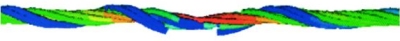
| QUESITO 13 : Sto eseguendo alcune analisi dinamiche non lineari (NonLinear Transient Dynamic Analysis). Le analisi in questione partono da una precedente analisi non lineare statica (Non Linear Static Analysis) nella quale è mia intenzione modellare una costruzione per fasi. Le Initial Conditions della NonLinear Transient Dynamic Analysis sono rappresentate perciò dallo step finale della NonLinear Static precedentemente eseguita. Il problema che riscontro è il seguente: · 1 - Sulla struttura registro degli stati tensionali completamente errati; · 2 - Diagrammando laccelerazione di un punto in testa alla struttura rispetto alla base fissa, riscontro una fase iniziale, che potremmo definire un transitorio, nel quale il programma attinge valori di accelerazione che sono di almeno due ordini di grandezza più grandi di quelli attesi. Dopo questa fase iniziale, la soluzione tende a stabilizzarsi intorno ad un valore di accelerazione che però continua ad essere molto diversa da quella attesa. Può trovare conferma di quanto le dico nel grafico "Accelerazione cresta" Sembrerebbe come se lanalisi partisse da condizioni iniziali rappresentate da velocità ed accelerazione diversa da zero. Sottolineo che questo problema continua ad osservarsi anche se assegno un accelerogramma completamente piatto. Questo tipo di problema è già stato osservato nelle analisi lineari con accelerogrammi, risolto in questo caso condensando tutte le condizioni di carico in un unico Primary Load Case, che rappresenta la Initial Conditions della Linear Transient Analysis. Mi sembra un espediente un po strano, ma lunico attraverso il quale riesco a risolvere questa anomalia del programma. Non è possibile ripetere lo stesso in una NonLinear Transient Dynamic Analysis perché in questo caso perderei completamente lo stato tensionale ricavato da una precedente Non Linear Static Analysis. |
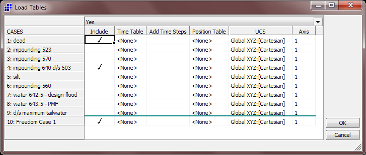
| RISPOSTA 13 : The reason your nonlinear transient dynamic (NTA) solution is not consistent with your nonlinear static (NLA) initial conditions is that the loads applied in the NTA are different to those applied in the last step of the NLA. Whereas the NLA loads at the last step contain only the following: - 1 x dead + 1 x impounding 640 d/s 503 the NTA solution includes all load cases in addition to the base excitation. To make the NTA solution consistent you need to switch off the other load cases. Please see the attached image. The NTA solver load tables can be used to scale applied load as a function of time. Where a load table is not used, then the load factor is assumed to be 1.0 when the load case is included. When the load case is not included, the load factor is effectively zero. Please see the Help file for additional description of the load tables setup in NTA. |
| QUESITO 12 : Con la presente Le chiedo se mi può indicare un metodo veloce per estrapolare le reazioni alla base si un setto in cemento armato. Come vede nella schermata sottostante, ho un setto molto irregolare e devo valutare le azioni in corrispondenza delle varie section cut: 1. orizzontale alla base 2. orizzontale in corrispondenza del cambio di sezione 3. verticake in corrispondenza della mensola Ho creato i grafici per le varie sollecitazioni (FZZ, FYY, FZX,FYZ, FXY, MYY, MZZ, MZY), ho calcolato l'area del grafico e mi servirebbe sapere in che modo posso estrarre i dati delle aree sottese dai grafici per le varie sollecitazioni (che mi danno la risultante dell'azione agente) in formato excel per calcolare le varie armature. Inoltre chiedo se mi può per favore indicare se MYYè il momento di rotazione attorno a Y nel piano di normale Y. |
| RISPOSTA 12 : Il momento MYY riferito agli assi globali è il momento che genera stress normale sui plate in direzione Y globale. Lo stesso vale per gli assi locali, solamente che si utilizza la notazione con y minuscolo. Trova sull'help di Straus7 tutte le informazioni sulle convenzioni di segno dei plate. Qui di seguito trova un pdf che spiega come estrarre i parametri delle sollecitazioni in setti mediante l'utilizzo dei "free body diagrams" senza passare per i grafici. E' un metodo meno oneroso ma altrettanto preciso. |
| QUESITO 11 : Le chiedo la cortesia di indicarci la sequenza di comandi per la visualizzazione della Progressione della formazione di cerniere plastiche fino al collasso come mostrato nell'esempio riportato sul Vostro sito per l'analisi di pushover di un telaio. |
| RISPOSTA 11 : Dopo aver fatto girare il modello, basta richiedere il contour di Yield Ratio, come indicato nella figura che segue. |
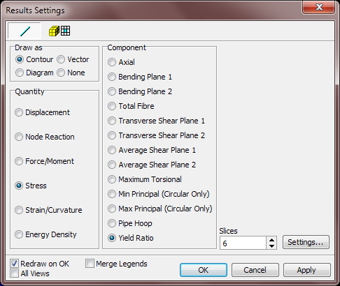
| QUESITO 10 : Un dubbio su Spectral Response: struttura con beam e plate - linear static - natural frequency - spectral response - scelgo i risultati di Spectral response - Result settings - scelgo BEAM contour stress total fiber ... e a questo punto sparisce la visualizzazione delle sezioni dei beam e appare solo la rappresentazione in wireframe delle sezioni stesse con la tabella a colori fiber stress tutta posta = a zero |
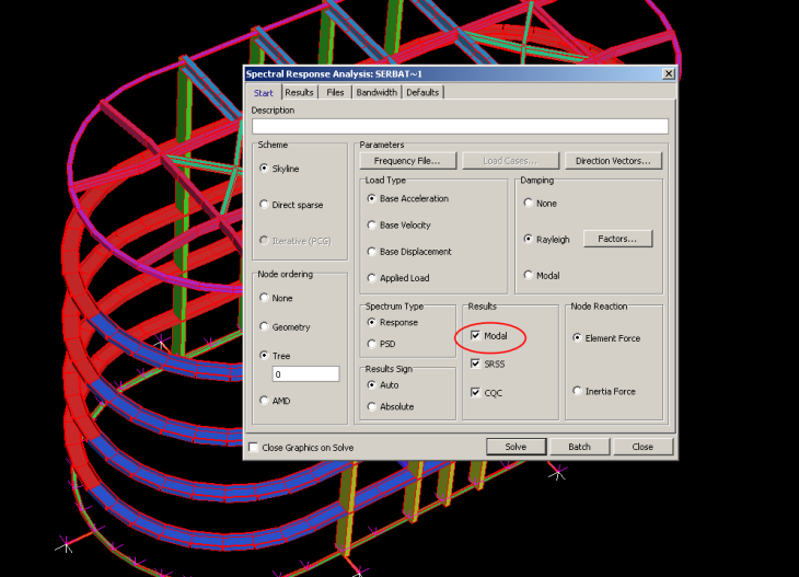
| RISPOSTA 10 : La sua osservazione è corretta, in quanto non sono stati salvati i risultati modali e pertanto il programma, senza di essi, non produce contour di stress negli elementi beam. Se oltre a SRSS e CQC spunta l'opzione "Modal" (immagine che segue) i risultati saranno visibili. |
| QUESITO 9 : Avrei necessità di comprendere quale è l'unità di misura in cui viene espressa la Engineering Modal Mass e la Engineering Modal Stiffness. L'Help in linea dice di far riferimento al manuale teorico. |
| RISPOSTA 9 : Per Modal Mass e Modal Stiffness si intendono i termini delle matrici rispettivamente di massa e rigidezza che vengono calcolate premoltiplicando e postmoltiplicando le matrici di massa e rigidezza globali della struttura per la matrice modale. Esse sono diagonali. L'unità di misura dei termini presenti in tali matrici è quella che utilizza il solutore (si vede nel file di log). Queste informazioni sono reperibili anche in rete (è sufficiente fare una ricerca con la chiave "modal mass"). Suggerisco di riferirsi ai coefficienti di partecipazione modale più che alla modal mass per vedere quanta massa partecipa al fenomeno vibrazionale. Le ricordo che il mass participation factor del modo i-esimo PF,i è pari a: PF,i = (fi,T x M x d0)^2 / (d0,T x M x d0) dove: fi è l'autovettore i-esimo (il modo di vibrare), M è la matrice delle masse del sistema (non la modale), d0 è un vettore di spostamenti e rotazioni che eccita la struttura rispetto agli assi globali. |
| QUESITO e RISPOSTA 8 : D1) Come posso modellare degli elementi a MOLLA con comportamento a sola compressione? R1) Sia con elementi "point contact" sia con elementi "spring". Consiglio di utilizzare i "point contact" per un contatto rigido a sola compressione, altrimenti utilizzare gli "spring" con una legge non lineare tra carico applicato e spostamento. D2) Con dei point contact "normal"? In questo caso, l'elemento beam che disegno come "point contact" che lunghezza deve avere? Oppure la lunghezza è indipendente dal comportamento? R2) La lunghezza deve essere tale da definire la superficie di contatto. Per esempio, se siamo nel piano medio di elementi plate, una lunghezza potrebbe essere metà dello spessore dei plate. La lunghezza non incide sulla rigidezza degli elementi di contatto in maniera diretta, ma può incidere (e questo dipende dal problema) sulla rigidezza del sistema. |
| QUESITO 7 : Per comprendere meglio l'impiego del materiale SOIL ho raffrontato i due modelli disponibili Mohr-Coulomb Soil (MC) e Linear Elasic Soil (LE) ottenendo però risultati a cui ho difficoltà dare una spiegazione: il modello LE valuta sempre la pressione orizzontale indotta dal peso del terreno anche quando non definisco la forza di gravità nel caso di carico. Svolgo correttamente l'analisi ? |
| RISPOSTA 7 : Forse l'utente non ha interpretato correttamente l'uso dell'elemento Soil. Il primo punto importante è che l'elemento Soil è inteso come elemento che funziona in presenza della gravita', quindi non ha senso togliere l'accelerazione verticale al secondo incremento come ha fatto l'utente. Il secondo punto è che occorre applicare correttamente il "In Situ Stress" prima di far partire l'analisi nonlineare. Non avendolo applicato, il programma non sa cosa fare e, avendo dato un Warning, procede ad applicare qualche valore di In-Situ Stress in base solo alla profondità e alla densità del materiale (questo viene applicato anche se non c'è la gravità). Il modo corretto di usare elementi Soil è il seguente : 1. Calcolare correttamente l'In-Situ Stress. Questo si può applicare come attributo (Attribute/Plate/Soil/In-Situ Stress), o meglio ancora con il tool Tools/Auto Assign/Soil In Situ Stress. 2. La gravità rimane per tutti gli incrementi. Nel primo incremento la gravità equilibra direttamente il In-Situ Stress applicato. Per un modello Soil preparato correttamente gli spostammenti verticali nel primo incremento dovrebbero essere praticamente nulli. Poi, quando si applicano i carichi, si sviluppano spostamenti e tensioni. 3. Non è consigliabile cambiare i valori delle Iteration Convergence Tolerance come è stato fatto dall'utente. Se il modello non converge, di solito questo significa qualcosa di importante. E' meglio lasciare i valori di default. 4. Se all'utente serve solo un material Mohr-Coulomb, allora è meglio usare l'elemente nonlineare Mohr-Coulomb invece del material Soil. |
| QUESITO e RISPOSTA 6 : D1- Il modello che abbiamo realizzato è molto semplice: travi e pilastri con beam (end relase alle travi poichè è una struttura prefabbricata), piani rigidi modellati con rigid link (auto assign--->restraints--->rigid connection--->piano XY ossia il piano di appartenenza dei solai). Per quanto riguarda la massa sismica come bisogna schematizzarla: traslazionale in X e Y o come massa non strutturale??? Ciò che volevamo fare noi è concentrare la massa di ogni singolo campo di solaio (tra 4 pilastri) nel nodo centrale che lega i rigid link. La suddivisione in campi è stata necessaria in quanto non abbiamo una distribuzione di masse uniforme sul e del solaio. R1 - Si può modellare in entrambi i modi (considererei anche la componente Z della massa comunque). La massa non strutturale è un po' più versatile come tipo di attributo (coefficiente dinamico, offset...). D2 - I contributi alla massa sismica ( G1, G2 e fi2*Qk) è necessario inserirli separatamente nei tre load case corrispondenti? R2 - non ci sono regole scritte a quanto mi risulta: tuttavia è sicuramente una buona cosa mantenere l'ordine e pertanto quella da voi suggerita sembra una buona suddivisione (optando quindi per le non structural mass). D3 - E' possibile visionare e ottenere le coordinate del Centro di massa e rigidezza della struttura? Come? R3 - Le coordinate del centro di massa sono reperibili nel menù summary->model, per quanto riguarda il centro di rigidezza, in Straus7 non è possibile tale visualizzazione. D4 - Analisi con spettro: Per quanto riguarda le 32 combinazioni sismiche e quelle statiche previste dalle NTC08 c'è modo di poterle avere o creare???e soprattutto qual'è il procedimento da dover seguire? Come viene introdotta l'eccentricità accidentale del Centro di Massa prevista da normativa per ottenere le 32 combinazioni? R4 - Risposta che richiederebbe molto spazio: consiglio di seguire il tutorial #5 - Spectral Response Analysis. Per quanto riguarda l'eccentricità accidentale del Centro di Massa è possibile modellare tutte le masse come non strutturali e attribuire loro un offset, altrimenti tale offset potrebbe essere indotto variando la densità delle parti. |
| QUESITO 5 : Le volevo chiedere come gestire un problema di non linearità nel modello che ho realizzato. Ho una galleria completamente interrata. Ho vincolato il mio modello con delle molle assegnate ai plate e reagenti solo a compressione. La galleria è soggetta a carichi verticali (peso proprio e peso del terreno gravante sulla calotta) e carichi orizzontali (spinta del terreno). Ho creato 4 Load Case e 2 Freedom Case. La domanda è la seguente: posso assegnare ai primi due Load Case il Fredom Case1 (in cui vincolo X adn Y TRanslation e Z Rotation) e poi assegnare ai secondi due Load Case (spinte orizzontali) il Freedom Case 2 (in cui vincolo X and Z Translation e Y Rotation)? Altrimenti non riesco ad arrivare a convergenza. |
| RISPOSTA 5 : Presti attenzione al fatto che quando va a vincolare le traslazioni e/o le rotazioni all'interno di un freedom case, il vincolo vale per TUTTI i nodi della struttura. Pertanto credo sia inopportuno, senza tuttavia entrare nel merito dell'analisi che sta svolgendo, vincolare la struttura in questo modo, a meno che non sia ciò che succede nella realtà. Conseguentemente, le ricordo che la scelta delle condizioni al contorno è condizionata dalla fisica del problema: nel suo caso ci sono dei vincoli elastici sulle pareti a sola compressione, mancano i vincoli in corrispondenza della fine dei tratti "cilindrici" (suppongo che questo sia un modello di un solo tratto di galleria). Le consiglio pertanto di liberare tutti i vincoli che ha settato nei Freedom Case e di cercare di riprodurre le condizioni al contorno reali assegnando vincoli come attributi (di faccia, come ha fatto correttamente nel modello, oppure nodali). Una nota sugli elementi plate: controlli l'orientamento in quanto ho notato che non tutti i plate hanno normale coerente (controlli i colori su entity display->plate tab->draw as: orientation). |
| QUESITO 4 : Avrei bisogno di sapere se è possibile (ed eventualmente quale procedura adottare) estrapolare le forze nodali in output ad una analisi spettrale. Tali forze nodali vengono poi utilizzate come assegnazione di un carico nodale equivalente a quello sismico ma sotto una condizione di carico statica. |
| RISPOSTA 4 : Non esiste un metodo automatico per farlo, ma con la seguente procedura si può fare semplicemente: 1. Lanciare la soluzione Spectral e sul pannello della Spectral Solver scegliere "Inertia Force" per l'opzione Node Reaction. 2. Aprire il risultato della soluzione Spectral. 3. Aprire Results Listings e scegliere il sub-tab Reactions (questo mostra le forze e i momenti generati dalle inerzie sui nodi, essendo i carichi statici equivalenti). 4. Copiare i valori dentro Excel. 5. Chiudere i risultati in Straus7. 6. Aprire l'Online Editor (Edit/Online Editor). 7. Scegliere il sub-tab Force (notare che se non si vede il sub-tab Force significa che il modello non contiene forze nodali.) 8. Mettersi in modalità Expanded View tramite il pulsante sopra. 9. Incollare le forze da Excel. 9. Ripetere la procedura per i momenti usando il sub-Tab Moments. |
| QUESITO 3 : A proposito dell'opzione API, quale è la compatibilità con i seguenti prodotti ? Windows 7 64bit Matlab 7.1 (R14) (in emulazione su sistema Windows 2000) Microsoft Visual Studio Express 2010 (32bit - 64bit??) |
| RISPOSTA 3 : Per Windows non fa differenza - sia 32-bit che 64-bit vanno bene. Per i linguaggi (es. C, C++, C#, Fortran, Delphi, Visual Studio, ecc.) bisogna compilare sempre come target 32-bit. Per gli ambienti tipo Excel, Matlab, ecc., bisogna usare le versioni a 32-bit. |
| QUESITO 2 : Il mio modello è un plinto su pali. Poichè esso è molto sollecitato da forze orizzontali, in quanto è la fondazione di una terra eolica, desideravo mettere in conto e quindi inserire nel modello: 1) il contributo dell'attrito all'interfaccia tra terreno e plinto; 2) molle alla winkler lungo i pali sempre per tenere conto del fatto che orizzontalmente i pali sono contenuti dal terreno. Non essendo riuscito a inserire nel modello i due punti precedenti vi scrivo così che mi possiate dire come fare. |
| RISPOSTA 2 : La risposta dipende in realtà da come ha modellato il plinto ed i pali. Presumo che abbia optato per una modellazione solida del plinto e a beam dei pali di fondazione. In ogni caso per rispondere al suo quesito: 1. il contributo dell'attrito del terreno sul plinto può essere considerato con elementi beam di tipo 'point contact' inserendo un opportuno valore del coefficiente di attrito coloumbiano. Con questo tipo di elementi si riesce anche a cogliere il comportamento a sola compressione del terreno nei confronti del plinto. 2. Il modello di winkler applicato ai pali può essere considerato come attributo ai beam che costituiscono i pali mediante il comando Attribute->beam->support. |
| QUESITO 1 : Devo modellare con elementi brick un elemento di cemento armato in cui inserire dei perni in acciaio (per simulare il fissaggio dei nodi trave pilastro dei capannoni industriali). Il problema è che i perni sono inseriti a secco, quindi devo vincolare i perni al cemento armato in modo che il vincolo offra solo rresistenza a compressione e non a trazione. (i perni lavorano a taglio). Ho pensato di vincolarli con elementi point contact ma il procedimento mi sembra lungo (andare a collegare migliaia di nodi con elementi asta è molto laborioso e sicuramente appesantirebbe a dismisura il modello). Vorrei sapere se in qualche modo fosse impossibile inserire tra il perno e il cemento armato un materiale (brick) che non offra resistenza a trazione. |
| RISPOSTA 1 : La modellazione del perno può essere trascurata inserendo un vincolo resistente solamente a compressione sulle facce degli elementi brick interessati dal collegamento. Questo però vale solamente nel caso in cui si voglia modellare la trave in CLS e non quello che sta a valle del collegamento (perno compreso). Il vincolo si trova su "attributes->brick->face support" ed è necessario spuntare l'opzione "compression only" per garantire la reazione alla sola compressione. Questo attributo richiede il solutore non lineare. Bisogna inoltre specificare un valore di rigidezza opportuno per tener conto dell'effettiva rigidezza del perno che si va a modellare con questo vincolo. |